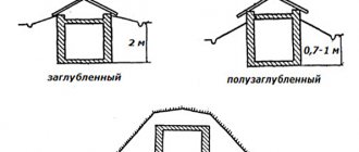
The presence of grounding in premises intended for residential use is important to ensure the safety of people from possible electric shock. Also, few people know about this to ensure the normal operation of electrical appliances.
When starting construction or purchasing a private house, first of all, you need to take care of the availability of grounding. You can see what the protective circuit looks like in the photo of grounding in a private house.
Grounding in the house is necessary if there are high-power electrical appliances, for example, a washing machine, heating devices, electric stove, microwave oven, etc. In addition, grounding can be used as a lightning rod.
Why do you need grounding in a private house: principle of operation
Grounding in a private home is considered an important part of the power supply system. It is installed for the following purposes:
- Protection of home inhabitants from electric shock (when touching a device with damaged electrical wiring insulation);
- Correct operation of modern electrical devices;
- Safe operation of gas equipment;
- Effective operation of lightning protection.
The principle of operation of the system is based on the elementary laws of physics, which say that electric current always moves in the direction of least resistance.
If the insulation of the device is damaged, the current flows out (short circuit) to the housing. This situation is fraught with malfunctions and breakdowns, not to mention the danger for a person to receive a sensitive discharge by accidentally touching the surface with his hand.
Grounding calculation formulas
The installation procedure for external and internal circuits in each region has a number of features. The selected model and the depth of the electrodes are influenced by the condition of the soil and its maximum resistance, the size of a private house and the number of household appliances, and the network voltage.
According to the requirements of state standards, for a voltage of 220 V in the network, the grounding must be 8 Ohms, for a voltage in the 380 V network, the grounding must be 4 Ohms.
To calculate the number of metal pins, special formulas are used. This stage of independent work should be approached with detailed attention, because errors in calculations often cause network malfunctions and electric shocks.
Video description
A succinct and clear grounding diagram for a private house, why it is needed and what it should be like, is shown in the following video:
If there is grounding, the current is distributed taking into account the resistance value of the body and the grounding loop of the house (in inverse proportion).
Carefully designed protective grounding creates an electrical circuit with a resistance significantly lower than that of the human body. The current passing through a person will not have a dangerous effect, and the main charge will go into the ground.
The passage of electric current through the human body in a system without grounding and with grounding Source plotnikov-pub.ru
The main element of grounding a private house is the grounding loop - the PUE defines it as metal conductors and grounding electrodes (rods or pipes) buried in the ground.
Internal electrical wiring according to modern standards is carried out with a three-wire wire (phase + neutral + ground). Protective grounding wires connect the circuit to electrical devices.
To ensure safety during thunderstorms, devices designed for this purpose are used - arresters designed for high currents and voltages.
Do-it-yourself grounding of devices
In order to ensure the safety of the residents of the house, you should approach the organization of the grounding loop competently and in detail.
It is important to take into account all the nuances and make all the appropriate calculations (taking into account the qualitative composition of the soil, its resistance, and the area of the residential building).
Instructions on how to make grounding at home with your own hands:
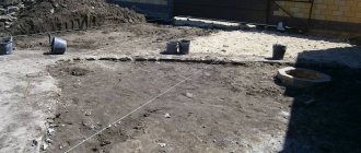
- First of all, you need to choose the right location for the circuit. The site is selected close to the main building, for example, at a distance of up to 200 cm. This approach will allow you to save on materials for the conductor.
- The trench for installation is dug in the shape of a triangle or a straight line, depending on the chosen configuration (can be seen in the grounding photo).
- The selected rods are driven into the ground to the calculated depth.
- The grounding conductors should be welded with a strip of metal, and a second such strip should be brought to the entrance to the residential building to connect to the circuit.
- All welding seams must be treated with an anti-corrosion compound or moisture-proof resin.
- The strip from the contour is brought to the base of the house, and a bolt is attached to the metal strip.
The final step is to attach the bolt with the conductor. The conductor itself should be placed in a shield and connected to the main grounding bus.
Video description
About the difference between TN and TT systems - in the video:
Decoding abbreviations
The first letter indicates the method of grounding the power source, the second characterizes the grounding of the consumer.
- T – source (consumer) is grounded;
- I – current-carrying parts of the source are isolated from the ground;
- N – the consumer is connected to the source grounding point (zeroed).
- C – conductors N (zero working) and PE (zero protective) are combined into one common conductor PEN;
- S – the functions of conductors N and PE are separated.
Subtypes of the TN system (TN-C, TN-S, TN-CS) differ in the method of connecting the N and PE conductors.
Grounding systems in alternating current networks Source zen.yandex.uz
TN-C system
In this case, one conductor (N and PE are combined throughout the entire electrical network) performs both operational and protective functions.
This method of organizing the system is ubiquitous in old housing stock; it is simple to implement and economical. But the absence of a separate protective grounding often leads to a short circuit during an emergency (power surges). According to modern standards, reflected in the requirements of the PUE, the TN-C grounding system is prohibited for new buildings. At the same time, there is no mandatory requirement to modernize old ones (unless major repairs are being done).
TN-S system
Here, the N and PE conductors are separated, and no voltage appears on the housings of electrical appliances. The system is safe and well protects people, household electrical equipment and the building. The main disadvantage is the high cost of arrangement.
TN-CS system
Combined system. At the output from the power source, conductors N and PE are combined in one conductor. A PE protective conductor is added at the entrance to the building.
When deciding which grounding is best for a private home, you should refer to the PUE code. He recommends the TN-CS subsystem as the main one for most consumers; it is simple to organize and more reliably protects against fire due to short circuit than others.
See also: Contacts of companies that provide electrical work services.
Differences between the TN-CS system Source keaz.ru
Checking the finished grounding
After completing all installation and connection operations of the ground loop, it is necessary to check it by measuring its electrical resistance. The parameters of this value should not exceed the limits specified in the regulatory documents.
You can use a simple test method at home. A light bulb from 100 to 150 W is connected between phase and ground.
Checking grounding performance using a lamp
Based on the glow of the lamp, conclusions are drawn:
- if the lamp does not light up, the grounding is done incorrectly;
- the lamp burning with a dim, dim light indicates a poor-quality connection of the ground loop elements or connections during connection;
- A bright lamp indicates good grounding performance.
During such a check, if there is an RCD in the circuit, it may operate, which indicates the operating condition of the circuit.
Check with a multimeter.
Checking grounding with a multimeter
It is carried out according to the following method:
- it is necessary to apply voltage by turning on the input circuit breaker;
- On the multimeter, select the voltage measurement mode;
- We connect the ends of the multimeter between the phase and neutral wires. The device should show a value around 220 volts;
- We make a similar measurement between the phase and the ground wire. The voltage may be slightly different from the previous measurement, but its very presence indicates the presence of ground;
- if there is no voltage, then there is no grounding, or it is not working.
The inspection can be entrusted to professionals. This check is shown in the video:
Checking the ground loop by professionals
Loop elements, grounding options and required materials
Protective grounding systems (grounding devices) are usually divided into the following elements:
- ground electrode (ground loop); there is a natural and artificial option;
- grounding conductors.
According to the PUE, it will be preferable to use a natural ground electrode (metal fence or pipeline) if its resistance meets the established standards. Otherwise, it is allowed to use an artificial ground electrode. For its construction you need:
- Metal for the ground electrode (pipe, smooth fittings, steel angle, rod, tape).
- A wire made of steel, copper or aluminum of sufficient cross-section.
- Fastening material (metal corners, clamps, couplings).
- Fastenings and insulation made of plastic.
What does modular-pin grounding consist of Source ecoask.ru
Modular-pin grounding
The grounding loop of a country house can be organized based on the modular-pin method. The system is extremely resistant to corrosion; no welding is used during installation. Pin grounding is assembled from steel rods up to 1.5 m long with a threaded connection. Copper-plated (or with a top layer of stainless steel) pins are driven into the ground with a vibrating hammer (perforator) with a special attachment. The electrodes (pins) are mounted at a great depth, so the circuit parameters do not depend on seasonal changes. The kit is usually purchased ready-made from the organization that handles the installation. The high cost of such a circuit is justified by its durability: the service life of copper-plated rods reaches 30 years, and of stainless steel – 50 years.
Modular grounding kit Source tirez.ru
Black metal outline
This design has a limited service life (5-10 years, due to corrosion); Over time, the circuit resistance deteriorates significantly. It is permissible to use black rolled metal with an anti-corrosion coating, but care must be taken that such a coating is not dielectric.
Operating principle of ground electrodes
Actually, the ground electrode is a set of conductors that are interconnected and located in the ground at different depths.
Depending on the point of placement of the rods, a distinction is made between loop and remote grounding.
- For the second option, the set of grounding conductors is completely removed outside the house or apartment.
- The first option is characterized by the location of grounding loops around the perimeter of the residential area.
The positive effect in this case is achieved by the uniform distribution of electrical potential over a certain area.
Requirements for the resistance of the grounding device.
Grounding for a private home makes sense if the circuit resistance is minimal. In this case (when the human resistance is much greater than the resistance of the circuit), an imperceptible charge will pass through the body, and the remaining potential will go into the ground.
Resistance is determined by the type, quantity and depth of grounding elements, as well as the properties of the soil. Loamy and clayey soils with a moisture content of 20-40% are considered optimal.
To ensure that the grounding device is performing its functions, a resistance measurement is carried out.
Rectangular or oval grounding pattern
Such schemes are also used in case of specific layout of the site and the condition of its soil. There may be large stones, buried structures, etc. in the ground. In any case, these contours are closed and are, as it were, a kind of triangular type. The installation principle of such circuits does not differ much from the triangular type.
All these types of grounding must be checked with a special device, but you can use a regular multimeter, and must correspond to a resistance value not exceeding 4 ohms, which is why it is important to follow all the rules for installing a protective circuit.
What to do when replacing old TN-C ground wiring
Most of the older housing stock had a two-wire power supply system installed. Even if grounding was installed, it was carried out according to the TN-C scheme, which uses a single “neutral” conductor to perform two tasks - working (for the operation of electrical appliances and devices) and protective (for preserving electrical network equipment).
In essence, such a system reliably protects the electrical circuit as a whole, but leaves powered household electrical appliances and their owners practically without protection. In addition, in wet weather, such a connection can lead to voltage surges even during a protective shutdown - there have been cases of death for similar reasons.
PEN conductor separation diagram Source tirez.ru
When constructing new houses, this system is not allowed; where it has been preserved, it is recommended, if possible, to switch to the TN-CS system (at the entrance to the building, the PEN wire is re-grounded and subsequently divided into PE and N). In an emergency, conductor N is disconnected from the network, protecting household electrical appliances and their owners from problems.
The transition to a TN-CS system in houses with worn-out electrical wiring is justified for safety reasons.
What to make metal connection from
Metal connection, i.e. The connection of electrodes driven into the ground is carried out using the following materials:
- Copper wire or bus, cross-sectional area - 10 square meters. mm and more.
- Steel tire, cross-section - 48 sq. mm.
- Aluminum wire or strip, cross-sectional area more than 16 square meters. mm.
For such purposes, a steel strip of 25-30x5 mm is preferable. The connection of such a strip to the electrodes is made using electric welding, which ensures a reliable connection. When using aluminum or copper conductors, the connection is made using a bolted connection.
Location of grounding device pins
Why do you need an RCD if there is grounding?
An RCD (residual current device) is a high-speed switch that works in tandem with a ground loop and responds to current leakage by breaking the circuit.
Operating principle of RCD Source tirez.ru
Circuit without grounding and RCD
When the insulation of a conductor is broken, a phase appears on the metal body of the electrical device. If the current has nowhere to go further, then when a person comes into contact with the body of an electrical device, the discharge will go through the body. The consequences will depend on many factors and the results can be different - from fear to interruptions in heart function.
Without grounding, the phase on the surface of the device with damaged wiring will remain until the input circuit breaker turns off .
RCD in a circuit without a protective conductor (TN-C)
In such a system, if the conductor insulation is broken, the RCD will not immediately operate, since no leakage current will occur. But as soon as a person touches the damaged device, part of the current will go into the body and the RCD will trip.
Even without grounding, current will flow through the human body only for the time required for the RCD to trip - usually tenths of a second. As a result, painful sensations are possible, but a fatal outcome can most likely be avoided.
Circuit with protective conductor (TN-S and TN-CS) and RCD
If an electrical appliance is in contact with the ground loop and is connected through an RCD, then if the phase conductor shorts to the metal body of the electrical appliance, leak immediately appears (which goes into the ground). The RCD trips and breaks the circuit.
Gas boiler and RCD
First of all, you need to understand that grounding a gas boiler in a private house must be carried out without fail - there are no exceptions.
Grounding the gas boiler and installing the RCD are carried out simultaneously. This is a necessary condition when connecting gas to a residential building, since surface tension forms on the body of the gas boiler during operation.
Grounding a gas boiler in a private home will avoid damage to expensive electronic equipment and prevent fire caused by static electricity. This measure, given the high explosiveness of the gas, serves as additional protection against fire.
All parts of a gas boiler must be grounded Source pinterest.com
Important point
In order to avoid having to expend a lot of effort when driving the grounding conductors, since this process is labor-intensive, it is advisable to buy rolled metal in advance with a smooth surface, which will definitely need to be sharpened with a grinder before starting operation.
External cable routing in corrugationPerforated cable tray: characteristics
- Wire connector: instructions on how to make the connection yourself. Instructions for use of clamp, clamp and lugs
Also, the process will be much easier for you if, during work, the soil located directly around the rod is “irrigated” from time to time with clean water.
What kind of work is done when installing grounding?
The entire process of creating a grounding loop is divided into the following stages:
- After determining the safe depth of the structure (where the soil is always wet), a trench is dug.
- Metal rods (grounding electrodes) are buried in the ground.
- A grounding loop is assembled: rods arranged in a row or in the shape of a figure (usually a triangle), connected with tape or pipes, and welded in series.
- The circuit is additionally welded to the down conductor with steel tape.
- The finished ground electrode is connected to the electrical panel, and the trench is backfilled.
During installation, competent specialists take into account some important nuances:
- The contour should be located below the soil freezing line. Otherwise, when the water in the ground turns to ice, the ground will stop conducting current and grounding will not work.
- Grounding electrodes cannot be painted, since the paint layer is a dielectric and there will be no contact of the circuit with the ground.
Grounding in a private house, circuit diagram Source asutpp.ru
Linear grounding diagram
Sometimes, due to the location of the site layout, it is impossible to install a triangular ground loop. In this case, a linear scheme is used, in which the electrodes are arranged in a single line.
Powder fire extinguishing from- Water in 19 liter containers: types and benefits of use
Slab fences
Because the circuit is not closed and does not have the same dispersion quality as a triangular one, the number of vertical electrodes should be brought to 5 pcs., the depth of the electrodes must be no less than the distance between them.
Isolated Neutral Systems
In all the systems described above, the neutral is connected to ground, which makes them quite reliable, but not without a number of significant drawbacks. Much more advanced and safer are systems that use an insulated neutral that is completely unconnected to ground, or grounded using special devices and devices with high resistance. For example, as in the IT system. Such connection methods are often used in medical institutions to power life-support equipment, at oil refining and energy plants, scientific laboratories with particularly sensitive instruments, and other critical facilities.
IT system
IT grounding system
The classic system, the main feature of which is the isolated neutral of the source - “I”, as well as the presence of a protective grounding circuit on the consumer side - “T”. Voltage from the source to the consumer is transmitted through the minimum possible number of wires, and all conductive parts of the consumer equipment housings must be reliably connected to the grounding electrode. There is no zero functional conductor N in the source-consumer section in the IT system architecture.
Grounding. What is it and how to make it (part 1)
My story will consist of three parts.
1 part. Grounding (general information, terms and definitions)
Part 2. Traditional methods of constructing grounding devices (description, calculation, installation)
Part 3. Modern methods of constructing grounding devices (description, calculation, installation)
In the first part (theory), I will describe the terminology, the main types of grounding (purpose) and the requirements for grounding.
In the second part (practice) there will be a story about traditional solutions used in the construction of grounding devices, listing the advantages and disadvantages of these solutions. The third part (practice) will in a sense continue the second. It will contain a description of new technologies used in the construction of grounding devices. As in the second part, listing the advantages and disadvantages of these technologies. If the reader has theoretical knowledge and is only interested in practical implementation, it is better for him to skip the first part and start reading from the second part.
If the reader has the necessary knowledge and wants to get acquainted only with new products, it is better to skip the first two parts and immediately move on to reading the third.
My view of the described methods and solutions is to some extent one-sided. I ask the reader to understand that I do not put forward my material as a comprehensive objective work and express my point of view and my experience in it.
Some part of the text is a compromise between accuracy and the desire to explain in “human language”, so simplifications are made that can “harm the ears” of a technically savvy reader.
1 part. Grounding
In this part I will talk about terminology, the main types of grounding and the quality characteristics of grounding devices.
A. Terms and definitions B. Purpose (types) of grounding
B1. Working (functional) grounding B2. Protective grounding
B2.1. Grounding as part of external lightning protection B2.2. Grounding as part of the surge protection system (SPD) B2.3. Grounding as part of the electrical network
B. Quality of grounding. Grounding resistance.
IN 1. Factors affecting the quality of grounding
B1.1. Contact area of the ground electrode with the ground B1.2. Electrical resistance of soil (specific)
AT 2. Existing standards for grounding resistance B3. Calculation of grounding resistance
A. Terms and definitions
To avoid confusion and misunderstanding in the further story, I will start from this point. I will give the established definitions from the current document “Rules for the Construction of Electrical Installations (RUE)” in the latest edition (Chapter 1.7 in the seventh edition).
And I will try to “translate” these definitions into “simple” language.
Grounding
is an intentional electrical connection of any point in the network, electrical installation or equipment with a grounding device (PUE 1.7.28).
Soil is a medium that has the property of “absorbing” electric current. It is also a certain “common” point in the electrical circuit, relative to which the signal is perceived.
Grounding device
- a set of grounding conductors/grounding conductors and grounding conductors (PUE 1.7.19).
This is a device/circuit consisting of a grounding conductor and a grounding conductor connecting this grounding conductor to the grounded part of the network, electrical installation or equipment.
Can be distributed, i.e. consist of several mutually distant grounding conductors. In the figure it is shown with thick red lines:
Ground electrode
- a conductive part or a set of interconnected conductive parts that are in electrical contact with the ground (PUE 1.7.15).
The conductive part is a metal (current-conducting) element/electrode of any profile and design (pin, pipe, strip, plate, mesh, bucket,
etc.) located in the ground and through which electric current from the electrical installation “flows” into it. The configuration of the ground electrode (number, length, location of electrodes) depends on the requirements for it and the ability of the soil to “absorb” the electric current flowing/“flowing” from the electrical installation through these electrodes. In the figure it is shown with thick red lines:
Ground resistance
— the ratio of the voltage on the grounding device to the current flowing from the ground electrode into the ground (PUE 1.7.26).
Grounding resistance is the main indicator of a grounding device, determining its ability to perform its functions and determining its overall quality. Grounding resistance depends on the area of electrical contact of the ground electrode (grounding electrodes) with the ground (“draining” of current) and the electrical resistivity of the soil in which this ground electrode is mounted (“absorption” of current).
Ground electrode (ground electrode)
- conductive part in electrical contact with local ground (GOST R 50571.21-2000 clause 3.21)
I repeat: the conductive part can be a metal (current-carrying) element of any profile and design (pin, pipe, strip, plate, mesh, bucket,
etc.), located in the ground and through which the electric current “flows” into it from electrical installations. In the figure they are shown with thick red lines:
Below are definitions that are not found or not described accurately enough in standards and norms, and therefore have only my description.
Grounding loop
is the “popular” name for a ground electrode or grounding device, consisting of several grounding electrodes (groups of electrodes) connected to each other and mounted around an object along its perimeter/contour.In the figure, the object is indicated by a gray square in the center, and the ground loop is indicated by thick red lines:
The electrical resistivity of the soil
is a parameter that determines the level of “electrical conductivity” of the soil as a conductor, that is, how well the electric current from the grounding electrode will spread in such an environment. This is a measured value that depends on the composition of the soil, the size and density of its particles adhering to each other, humidity and temperature, and the concentration of soluble chemicals in it (salts, acidic and alkaline residues).
B. Purpose (types) of grounding
Grounding is divided into two main types according to the role it performs - working (functional) and protective. Also, various sources provide additional types, such as: “instrumental”, “measuring”, “control”, “radio”.
B1. Working (functional) grounding
This is the grounding of a point or points of live parts of an electrical installation, performed to ensure the operation of the electrical installation (not for electrical safety purposes) (PUE 1.7.30).
Working grounding (electrical contact with the ground) is used for the normal functioning of an electrical installation or equipment, i.e. for their operation in NORMAL mode.
B2. Protective grounding
This is grounding performed for electrical safety purposes (PUE 1.7.29).
Protective grounding ensures the protection of electrical installations and equipment, as well as the protection of people from the effects of dangerous voltages and currents that may occur during breakdowns, improper operation of equipment (i.e. in EMERGENCY mode) and during lightning strikes. Protective grounding is also used to protect equipment from interference during switching in the power supply network and interface circuits, as well as from electromagnetic interference induced from nearby equipment.
The protective purpose of grounding can be considered in more detail using two examples:
- as part of an external lightning protection system in the form of a grounded lightning rod
- as part of a surge protection system
- as part of the facility's electrical network
B2.1. Grounding as part of lightning protection
Lightning is a discharge or, in other words, a “breakdown” that occurs FROM the cloud TO the ground, when a charge of a critical value (relative to the ground) accumulates in the cloud.
Examples of this phenomenon on a smaller scale are “breakdown” (wiki) in a capacitor and gas discharge (wiki) in a lamp. Air is a medium with a very high resistance (dielectric), but the discharge overcomes it, because has great power. The discharge path follows areas of least resistance, such as water droplets in the air and trees. This explains the root-like structure of lightning in the air and the frequent strikes of lightning into trees and buildings (they have less resistance than the air in this gap). When it hits the roof of a building, lightning continues its path to the ground, also choosing areas with the least resistance: wet walls, wires, pipes, electrical appliances - thus presenting a danger to people and equipment located in this building.
Lightning protection is designed to divert lightning discharge from the protected building/object.
A lightning discharge, following the path of least resistance, enters a metal lightning rod above the object, then, along metal lightning rods located outside the object (for example, on walls), descends to the ground, where it diverges in it (I remind you: soil is a medium that has the property of “absorbing ” into itself an electric current). In order to make lightning protection “attractive” to lightning, as well as to prevent the spread of lightning currents from lightning protection parts (receiver and taps) into the object, its connection to the ground is made through a ground electrode having a low grounding resistance.
Grounding in such a system is a mandatory element, because it is this that ensures the complete and rapid transition of lightning currents into the ground, preventing their spread throughout the facility.
B2.2. Grounding as part of a surge protection system (SPD)
The SPD is designed to protect electronic equipment from a charge accumulated on any part of the line/network as a result of exposure to an electromagnetic field (EMF) induced from a nearby powerful electrical installation (or high-voltage line) or EMF arising from a close (up to hundreds of meters) discharge lightning.
A striking example of this phenomenon is the accumulation of charge on the copper cable of a home network or on the “forwarding” between buildings during a thunderstorm. At some point, the devices connected to this cable (computer network card or switch port) cannot withstand the “size” of the accumulated charge and an electrical breakdown occurs inside this device, destroying it (simplified). To “bleed off” the accumulated charge parallel to the “load,” an SPD is placed on the line in front of the equipment.
A classic SPD is a gas arrester (wiki), designed for a certain “threshold” of charge, which is less than the “safety factor” of the equipment being protected.
One of the electrodes of this arrester is grounded, and the other is connected to one of the line/cable wires. When this threshold is reached, a discharge occurs inside the spark gap between the electrodes. As a result, the accumulated charge is discharged into the ground (through grounding).
As in lightning protection, grounding in such a system is a mandatory element, because it is this that ensures the timely and guaranteed occurrence of a discharge in the SPD, preventing the charge on the line from exceeding a level that is safe for the equipment being protected.
B2.3. Grounding as part of the electrical network
The third example of the protective role of grounding is ensuring the safety of humans and electrical equipment during breakdowns/accidents.
The simplest way to describe such a breakdown is a short circuit of the phase wire of the electrical network to the body of the device (short circuit in the power supply or short circuit in the water heater through the aqueous medium). A person who touches such a device will create an additional electrical circuit through which a current will flow, causing damage to internal organs in the body - primarily the nervous system and heart.
To eliminate such consequences, the housings are connected to a grounding conductor (to drain emergency currents into the ground) and automatic protective devices are used that turn off the current in a split second in an emergency.
For example, grounding of all cases, cabinets and racks of telecommunications equipment.
B. Quality of grounding. Grounding resistance.
For grounding to perform its functions correctly, it must have certain parameters/characteristics. One of the main properties that determine the quality of grounding is the resistance to current spreading (grounding resistance), which determines the ability of the grounding electrode (grounding electrodes) to transmit currents supplied to it from the equipment into the ground. This resistance has finite values and, ideally, is a zero value, which means the absence of any resistance when passing “harmful” currents (this guarantees their COMPLETE absorption by the soil).
IN 1. Factors affecting the quality of grounding
Resistance mainly depends on two conditions:
- area (S) of electrical contact of the ground electrode with the ground
- electrical resistance (R) of the soil itself in which the electrodes are located
B1.1. Contact area of the ground electrode with the ground.
The larger the area of contact between the ground electrode and the ground, the larger the area for the current to pass from this ground electrode into the ground (the more favorable conditions are created for the current to pass into the ground).
This can be compared to the behavior of a car wheel when turning. A narrow tire has a small contact area with the asphalt and can easily begin to slide along it, “sending” the car into a skid. A wide tire, and even a little flat, has a much larger contact area with the asphalt, providing reliable grip and, therefore, reliable control of movement. (The example turned out to be illiterate. Thanks to SVlad - comment: habrahabr.ru/post/144464/# comment_4854521) You can increase the contact area of the ground electrode with the ground either by increasing the number of electrodes, connecting them together (by adding the areas of several electrodes), or by increasing the size of the electrodes. When using vertical grounding electrodes, the latter method is very effective if the deep layers of the soil have lower electrical resistance than the upper ones.
B1.2. Electrical resistance of soil (specific)
Let me remind you: this is a quantity that determines how well the soil conducts current through itself.
The less resistance the soil has, the more efficiently/easier it will “absorb” the current from the ground electrode. Examples of soils that conduct electricity well are salt marshes or highly moist clay. The ideal natural environment for passing current is sea water. An example of a “bad” soil for grounding is dry sand.
(If interested, you can look at the table of soil resistivity values used in the calculations of grounding devices).
Returning to the first factor and the method of reducing grounding resistance in the form of increasing the depth of the electrode, we can say that in practice, in more than 70% of cases, soil at a depth of more than 5 meters has several times lower electrical resistivity than that of the surface, due to higher humidity and density . Groundwater is often found, which provides the soil with very low resistance. Grounding in such cases is very high quality and reliable.
AT 2. Existing standards for grounding resistance
Since the ideal (zero spreading resistance) cannot be achieved, all electrical equipment and electronic devices are created based on certain standardized values of grounding resistance, for example 0.5, 2, 4, 8, 10, 30 or more ohms.
For orientation, I will give the following values:
- for a substation with a voltage of 110 kV, the current flow resistance should be no more than 0.5 Ohm (PUE 1.7.90)
- When connecting telecommunications equipment
, grounding should usually have a resistance of no more than 2 or 4 ohms - For reliable operation of gas arresters in devices for protecting overhead communication lines
(for example, a local network based on a copper cable or a radio frequency cable), the grounding resistance to which they (the arresters) are connected must be no more than 2 Ohms. There are instances with a requirement of 4 ohms. - at the current source (for example, a transformer substation), the grounding resistance should be no more than 4 Ohms at a linear voltage of 380 V of a three-phase current source or 220 V of a single-phase current source (PUE 1.7.101)
- the grounding used to connect lightning rods
should have a resistance of no more than 10 ohms (RD 34.21.122-87, p.
- for private houses, with a connection to a 220 Volt / 380 Volt power supply: when using the TN-CS system, it is necessary to have local grounding with a recommended resistance of no more than 30 Ohms (I am guided by PUE 1.7.103)
- when using the TT system (isolating grounding from the neutral of the current source) and using a residual current device (RCD) with an operating current of 100 mA, it is necessary to have local grounding with a resistance of no more than 500 Ohms (PUE 1.7.59)
AT 3. Calculation of grounding resistance
To successfully design a grounding device that has the required grounding resistance, standard grounding configurations and basic formulas for calculations are usually used.
The ground electrode configuration is usually selected by the engineer based on his experience and the possibility of its (configuration) application at a particular facility.
The choice of calculation formulas depends on the selected grounding configuration. The formulas themselves contain the parameters of this configuration (for example, the number of grounding electrodes, their length, thickness) and the parameters of the soil of a particular object where the ground electrode will be located. For example, for a single vertical electrode this formula will be:
The accuracy of the calculation is usually low and again depends on the soil - in practice, discrepancies in practical results occur in almost 100% of cases. This is due to its (soil) great heterogeneity: it changes not only in depth, but also in area - forming a three-dimensional structure. Existing formulas for calculating grounding parameters can hardly cope with one-dimensional soil heterogeneity, and calculations in a three-dimensional structure involve enormous computing power and require extremely high operator training. In addition, to create an accurate soil map, it is necessary to carry out a large amount of geological work (for example, for an area of 10*10 meters it is necessary to make and analyze about 100 pits up to 10 meters long), which causes a significant increase in the cost of the project and is most often not possible.
In light of the above, the calculation is almost always a mandatory but indicative measure and is usually carried out on the principle of achieving a grounding resistance of “no more than.” The average values of soil resistivity, or their largest values, are substituted into the formulas. This provides a “margin of safety” and in practice is expressed in obviously lower (lower means better) grounding resistance values than expected during the design.
Construction of ground electrodes
When constructing grounding electrodes, vertical grounding electrodes are most often used.
This is due to the fact that horizontal electrodes are difficult to bury to a great depth, and at a shallow depth of such electrodes, their grounding resistance greatly increases (deterioration of the main characteristic) in winter due to the freezing of the top layer of soil, leading to a large increase in its specific electrical resistance. Steel pipes, pins/rods, angles, etc. are almost always chosen as vertical electrodes. standard rolled products having a large length (more than 1 meter) with relatively small transverse dimensions. This choice is due to the possibility of easily deepening such elements into the ground, unlike, for example, a flat sheet.
More details about construction in the following parts.
Continuation:
- Second part
- The third part
Alexey Rozhankov, technical specialist
The following materials were used in preparing this part:
- Publications on the website “Grounding on ZANDZ.ru”
- Rules for the Construction of Electrical Installations (PUE), part 1.7 as amended by the seventh edition (Google)
- GOST R 50571.21-2000 (IEC 60364-5-548-96) Grounding devices and electrical potential equalization systems in electrical installations containing information processing equipment (Google)
- Instructions for the installation of lightning protection of buildings and structures RD 34.21.122-87 (Google)
- Own experience and knowledge
So which circuit should you choose?
Let's first figure out under what conditions certain types of circuits are used.
Closed triangular outline:
- The 220/380V network is brought into the house through a power input panel.
- Continuous total power consumption is more than 3 kW.
- Availability of industrial-type electrical appliances with a provided grounding connection (lathe, circular saw, drilling machine, etc.).
Two groups of linear grounding conductors:
- The total power consumption is over 1 kW for 20 minutes.
- The electrical wire is routed underground through an external panel.
- The house has at least one of the communications (communications, gas, water, sewerage).
There are many other factors, so in this case it is best to consult a specialist and do the work yourself.